
|
Doulton - Water Filtration Systems |
Installation, Cleaning and Troubleshooting Guide
Special Note: If you are in doubt, at any phase of the installation, please contact a certified plumber or the company directly, email - h20@doulton.ca or call 1-800-439-1671.
Section 2: HIP/HIS Series - Under Counter Water Treatment Systems
A. Installation
B. Flushing
C. Cleaning and Maintenance
D. Troubleshooting
 A. FILTER HOUSING
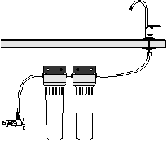
1. For small one to three stage systems, select a suitable location for the filter housing(s) under the kitchen sink or on the under sink doors. The doors can be an advantage for persons who have trouble bending or reaching. Remember this unit must be 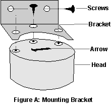 serviced at regular intervals. Therefore the system should be reasonably accessible to enable the sump to be unscrewed to change or clean the cartridge(s). A clearance of 10 inches is desirable for ease of removal.
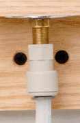
2. Fit the head of the filter housing to the bracket using the 3 self-tapping screws provided (Fig A.). Ensure the bracket corresponds to the arrow on the head, indicating the direction of water flow.
3. Secure the bracket to the wall or door with the two screws provided. For multi-stage units the short hose inter-connecting the head assemblies should be installed before the heads are mounted to the wall. Refer to Section 2, Para 12 below.
4. SHUT OFF THE WATER SUPPLY TO THE SINK. Select a suitable position for the location of the line piercing saddle valve on the copper (or plastic) COLD water line leading to the main faucet. Ensure that the saddle valve is located ABOVE the sink shut-off valve (if you have one). It must also be accessible enough to allow for isolation of the filter during cleaning or replacement of the cartridge(s).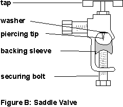
5. Back off the tap FULLY to retract the piercing tip into the washer.
6. Back off the securing bolt and remove the pipe backing sleeve. Match the curvature of the sleeve to the size of your main water line.
7. Slide the valve around the line and tighten the securing bolt until it butts up firmly against the sleeve. Do not tighten to the point of crushing the line.
8. Turn the tap in until you feel the piercing tip contact the water line. Turn the tap in and out in increasing amounts until you feel the tap turn freely inward. It has then penetrated the line fully. Continue turning in until it bottoms out. Leave the tap turned fully in. This is the "off" position.
 C. FAUCET
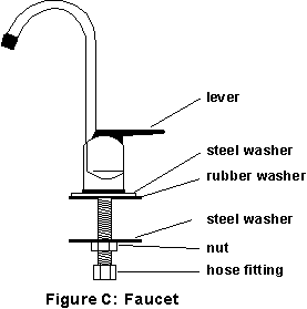
9. Select a suitable position for the faucet as close to the sink edge as practical, but ensuring access from the underside to enable installation of the mounting hardware and hose.
10. Mark and drill the faucet hole (1/2 inch.) with a suitable bit for the surface being penetrated.
11. Assemble the faucet as shown in Fig C.
 D. HOSE CONNECTIONS
12. Cut the hose to the desired length between the saddle valve and the head. Leave enough slack to be able to secure the hose out of the way.
13. Install the nut, insert and sleeve as shown in Fig D and secure to the saddle valve.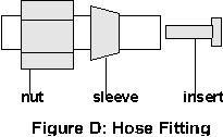
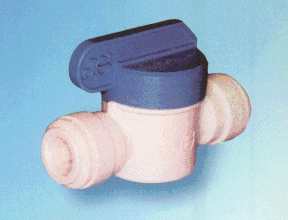 14. Push the other end of the hose into the "John Guest Push-Fit" connector on one end of the Ball Valve. Using a separate three (3) inch piece of hose (cut from the remaining stock) push one end into the Ball Valve and the other into the John Guest fitting in the head. Place the Ball Valve in the "OFF" position which is with the handle at 90 degrees to the hose.
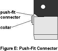 Note:The hose may be easily removed from a John Guest fitting by pushing the collar on the push-fit connector all the way in and holding it there while gently pulling back on the hose. Excessive force is not required.
15. Repeat these procedures for the hose between the faucet and the head.
16. Inspect the cartridge(s) for obvious damage prior to installation.
17. Ensure that the rubber washer is in position over the threaded end of the cartridge.  Lubricate this washer and the "O" ring in the top of the sump with a small amount of "Vaseline" or any equivalent petroleum jelly. DO NOT USE MINERAL OIL. Tighten the cartridge into the head. The cartridge should butt up and slightly compress the washer, but it does not have to be
 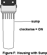 tightened into place with anything other than wrist pressure.
18. Slide the housing sump(s) over the cartridge(s) and screw on until tight. Once again wrist pressure is sufficient.
note:Where clearance is restricted it may be necessary to slide the housing sump over the cartridge before the cartridge is screwed into the head. Ensure that sufficient room remains to grip the cartridge while screwing it into the head.
19. Turn on the main water supply. While closely observing for leakage, slowly open (counter clockwise) the saddle valve fully and then the Ball Valve (in-line with hose).
20. Lift the faucet lever up to lock it in the fully open position to discharge the air from the system.
21. Let the system run for 1 to 2 minutes to flush out any loose carbon (black) dust left over from manufacturing.
22. Monitor the system closely for leaks or manufacturing defects for 24 hours.
1. The flow rate from your filter will decrease over a period of time. This is due to the pores in the ceramic cartridge becoming plugged by bacteria, dirt, asbestos fibers or any other particles in your water supply.
Note: Remember this cartridge is sub micron rated so in rural areas with high sediment levels, this could be frequent. If flow reduction is too frequent, then this is a sign that you should be using a pre-filter such as a 5 micron CP0500. Call the technical support line for more information.
2. The ceramic cartridge may be removed and cleaned by turning ON the drinking water faucet (to release the water pressure) and then turning off the water supply to the filter. Leave the faucet ON throughout this procedure. To shut off the water, turn the John Guest Ball Valve shut-off 90degrees to the hose, or if your unit does not use a ball valve shut-off then turn the T handle of the SV2002 saddle valve at the cold water connection CLOCKWISE until the water flow stops. Either method will isolate the filter system from the main water line.
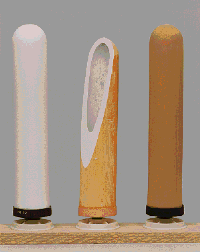 |
Note: The photo on the left shows a new white ceramic, a cutaway of a slightly dirty ceramic in the middle and a very dirty ceramic on the right. The middle cutaway ceramic illustrates how bacteria and particulate matter (dirt) is trapped on the outer wall of the ceramic as the water passes through to the center. |
 |
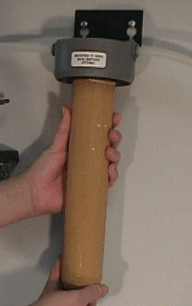
| 3. Place a shallow pail under the sump when removing it as it is full of water and a small amount may spill. Unscrew the sump, sliding it down and completely clear of the ceramic. Remember the ceramic is very fragile and will not withstand force being applied to the side of the element. Dump the water from the sump and set it aside, ready for re-installation. | ||
 |
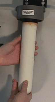
4. Firmly grip the ceramic and unscrew the element, it is now ready for cleaning. | 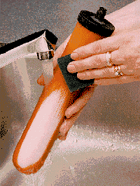 |
| 5. Using a stiff brush, or scouring pad, scrub the outer surface of the ceramic under running water until it returns to a uniform off white colour (yellow tint). Do not scrub too close to the mount. This is the area most prone to accidental breakage during installation or removal so it is best to keep the ceramic as thick as possible next to the mount. CAUTION: Always keep the inlet up(threaded mount) and do not allow the inlet to come into contact with the running water. Note: Never use soaps, detergents, bleach, or any other chemical during the cleaning process. These could harm the performance of your unit. Excessive cleaning shortens the life of the ceramic substantially. |
||
|
6. Inspect the large rubber washer at the base of the mounting threads for any signs of damage. Lubricate this washer and the "O" ring in the top of the sump with a small amount of "Vaseline" or any equivalent petroleum jelly. DO NOT USE MINERAL OIL.
Note:If this washer appears to be missing from the cartridge, check the inside of the "head" as it may have stuck there. |
 |
| 7. Hand tighten the cartridge(s) into the head(s). Carefully slide the sump under the cartridges and into position. Hand tighten the sump to the head, slowly turn on the John Guest ball valve or the saddle valve, and let the system flush for 1 minute. |
8. For MULTI-STAGE UNITS. At the recommended replacement timing [refer to the specification sheet for your cartridges, follow all of the above steps except for the cleaning phase. Seal the removed cartridges in a plastic bag and dispose of it as you would for chemicals such as paint or oil.
1. If you discover any evidence of seepage from the system:
2. If you cannot obtain water flow through the filter.
If all else fails, call our North American Technical Support Line 1-800-439-1671 or describe your problem via
Email to h2o@doulton.ca
// Overview // Index // Health // History // Technologies // FAQ // Employment // Training //
// Product Catalogue// Travel // Research // Test Results // Orders / Prices // What's New // Contact Us //
Copyright © 1997 H2O International Inc. All rights reserved.